Abstract: This paper elaborates on the principles and differences between 6-pulse and 12-pulse rectifiers in four aspects: theoretical derivation, measured data analysis, harmonic analysis and improvement countermeasures, and performance comparison. It provides an in-depth and comprehensive analysis of the rectification technology for high-power UPS.
1. Theoretical Derivation
1. Principle of 6-pulse rectifier:
6-pulse refers to full-bridge rectification composed of 6 thyristors. Since there are 6 switching pulses that control each of the 6 thyristors respectively, it is called 6-pulse rectification.

When the commutation process and current ripple of the three-phase bridge thyristor rectifier circuit are ignored, assuming that the AC-side reactance is zero, the DC-side inductance is infinite, and the delay firing angle α is zero, the AC-side current can be expanded into Fourier series as follows:
 (1-1)
From Equation (1-1), the following conclusions can be drawn:
The current contains 6k−1 (k is a positive integer) order harmonics, namely 5, 7, 11, 13.... The effective value of each harmonic is inversely proportional to the harmonic order, and the ratio of the effective value of each harmonic to that of the fundamental wave is the reciprocal of the harmonic order.
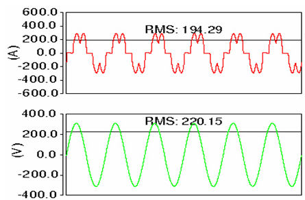
Fig. 1.1 Input voltage and current waveforms of 6-pulse phase A obtained by computer simulation
2.Principle of 12-Pulse Rectifier:
12As shown in the figure below, the two three-phase rectification circuits I and II form a 12-pulse rectification circuit through different connections of the transformer.

12 Schematic diagram of a pulse rectifier (composed of 2 parallel 6-pulse units)
The Fourier series expansion of the grid-side current of Bridge I is:
 (1-2)
The grid-side line voltage of Bridge II leads that of Bridge I by 30°, so the grid-side line current leads that of Bridge I by 30°
 (1-3)
Therefore, the resultant grid-side line current
 (1-4)
It can be seen that the 5th, 7th, 17th, 19th, ... order harmonics generated by the two rectifier bridges cancel each other out. Only the 12k−1 (k is a positive integer) order harmonics are injected into the power grid, namely the 11th, 13th, 23rd, 25th and other order harmonics. The effective value of these harmonics is inversely proportional to the harmonic order, and the ratio of the effective value to the effective value of the fundamental wave is the reciprocal of the harmonic order.

Fig. 1.2 Input voltage and current waveforms of phase A of 12-pulse UPS obtained from computer simulation
II. Analysis of Measured Data.
The above calculation is performed under ideal conditions, with many factors ignored, such as commutation process, DC-side current ripple, trigger delay angle, AC-side reactance and other factors. Therefore, there are certain discrepancies between the measured values and the calculated values.
Harmonic table obtained from theoretical calculation:

Measured harmonic data table of a certain type of high-power UPS:

From the comparison of the above two tables, it can be concluded that 6-pulse rectifier has the maximum harmonic content at the 5th harmonic, and the harmonic of 12-pulse rectifier with the largest amplitude is the 11th harmonic, which is consistent with the theoretical calculation results. For the 6-pulse rectifier, the measured value of the 5th harmonic is larger than the calculated value, while for the 12-pulse rectifier, the measured value of the 11th harmonic is consistent with the calculated value.
3. Harmonic Analysis and Improvement Countermeasures
Harmonics can cause adverse consequences such as overheating of distribution cables and transformers, degraded call quality, false tripping of air circuit breakers, and generator surge; According to the current phase sequence, harmonics are classified into +sequence (3k+1th, where k is 0 and positive integers), -sequence (3k+2th, where k is 0 and positive integers), and 0sequence (3kth, where k is a positive integer).
Positive sequence current increases power loss,negative sequence current causes the motor to reverse and overheat,zero sequence current leads to an abnormal increase in neutral line current.
It can be seen from the measured values that for a6-pulse rectifier, the5th harmonic is the largest, and a 5th harmonic filter can be installed to suppress harmonics; for a12-pulse rectifier, the11th harmonic is the largest, and an 11th harmonic filter can be added for harmonic suppression. The schematic diagram of the filter is as follows:
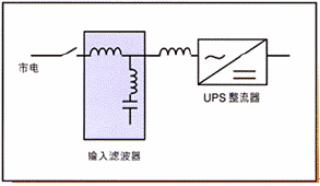
Figure: Schematic diagram of a commonLC filter
A certain model of high-powerUPSharmonic comparison table after adding a filter is as follows:
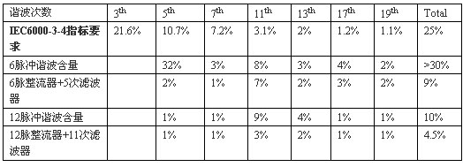
It can be seen from the above table that the harmonic suppression effect of adding the filter is very obvious.
It should be particularly noted that:6-pulse + 5th harmonic filter configuration can meet the harmonic requirement of around 9%. However, since the 5th harmonic (250Hz) filter has a relatively large capacitance, when the UPS load is light (<15% of the rated load), the input current of the rectifier will lead the input voltage. If the excitation winding of the generator adopts self-excitation mode, it is easy to generate armature positive feedback effect, and the output voltage of the generator will rise abnormally, causing the generator to enter protection state and shut down. Therefore, the 6-pulse + 5th harmonic filter scheme is not recommended for use when the UPS load is light. When the actual load is light, the 5th harmonic filter can be disconnected from the rectifier.
A standalone 12-pulse rectifier can also achieve a current harmonic index of around 10%. However, it eliminates the large-capacitance LC circuit, thus avoiding the positive feedback effect with the generator excitation.
By adopting a 12 pulse rectifier + 11th order harmonic filter, a current harmonic index of less than 4.5% can be achieved. Both individual harmonic components and total harmonic content meet the index requirements specified in IEC61000-3-4.
Appendix 1: Total input current harmonic content data under different load configurations
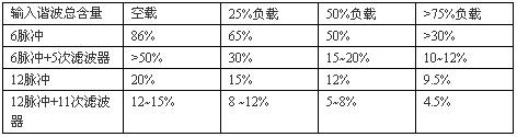
Appendix 2: Table of Total Input Current Harmonic Content for a Certain Model of 400KVA 12-pulse + 11th-order Filter UPS

It is the absolute value of harmonic current rather than the percentage of harmonic current that affects the power grid. It can be seen from the above table that under full load condition, the absolute value of harmonic current reaches the maximum; under half load and light load conditions, the absolute value of harmonic current does not exceed 100% of that under full load condition. The 12-pulse + 11th-order harmonic filter features the lowest effective total input current harmonic, and can also avoid the drawbacks of active filters such as “incorrect compensation” and low system efficiency. Therefore, the 12-pulse + 11th-order harmonic filter causes the least pollution to the power grid and is suitable for applications with high reliability requirements.
IV. Performance Comparison:
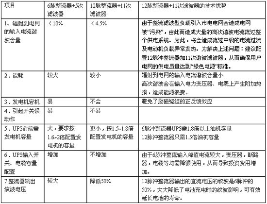
As can be seen from the table above, 12-pulse rectifiers outperform 6-pulse rectifiers in multiple performance indicators. Since its emergence in the 1970s, 12-pulse rectification technology has been continuously improved and refined, and has gradually become the preferred technology for high-power UPS rectifiers. All leading global high-power UPS manufacturers have launched 12-pulse UPS products.
In conclusion, when the investment budget allows, try to choose the UPS configuration of 12-pulse rectifier plus 11th harmonic filter. This configuration meets the Class I requirements for input current harmonic components in the UPS industry standard of the Ministry of Information Industry of China (YD/T1095-2000) and the index requirements of the International Electrotechnical Commission IEC61000-3-4.